WASTEWATER TREATMENT PROCESS DESIGN CALCULATOR | NO 4
Activated sludge process – Secondary clarifier sizing
Objectives:
-
Calculate size of secondary clarifier
-
Calculate blower discharge head required
-
Convert blower size to field condition suction side conditions
Theoretical basis:
Design Philosophy (Courtesy: reprint from CPHEEO manual on wastewater engineering 2013)

Calculator
(Note – all Yellow are user defined value, all white are fixed values,
all green are calculated value, all orange is calculated not to be
shown)
Instructions
Enter values highlighted in the
Yellow
Green highlights
are the results
In case of
any invalid result of non-functioning of the calculator, please write
to us at urvpatel@swaenviro.com. We will try and help you with your
sizing and calculation
INPUT
| Parameter | Value | Unit | Remarks |
|---|---|---|---|
| Flowrate | MLD | Ultimate build out capacity | |
| 41.67 | cum/hr | ||
| Recirculated flow | 5.00 | % | Assumed 5 % |
| Recirculated flowrate | 2.08 | cum/hr | |
| Average flowrate | 0.01 | cum/s | |
| Peak factor | 3 for <2 MLD, 2.5 for <3.5 MLD , 2.25 for 5MLD | ||
| Peak flowrate | 0.035 | cum/s | |
| Assumed RAS flowrate | fraction of plant flow rate | Maximum assumed for peak loading ; In reality it would range from 0.3-1 of the average plat capacity | |
| RAS flow | 1000 | cum/day | |
| 41.67 | |||
| Design Calculations | |||
| Tank sizing -As per conventional ASP | |||
| Solids loading rate | kg/sqm-day | 25-120 kg/sqm-day for average flow | |
| Surface area required as per SLR | 26.25 | sqm | Based on 100 % RAS flow rate of average and above SLR |
| Solids loading rate (Peak) | kg/sqm-day | 170 kg/sqm-day for peak flow; | |
| Surface area required as per SLR (Peak) | 71.47 | sqm | Based on 100% RAS + Peak & Recirculated |
| Surface overflow rate | cum/sqm-day | 8-12 cum/sqm-day for average flow; As per CPHEEO Nov-2013 Section 5.7.4.2.5, Table 5.8, Page 5.53 8-15 cum/sqm-day for average & 25-35 cum/sqm-day for peak; | |
| Surface area required as per SOR | 70.00 | sqm | Average + Recirculated |
| Surface overflow rate (Peak) | cum/sqm-day | As per CPHEEO Nov-2013 Section 5.7.4.2.5, Table 5.8, Page 5.53 8-15 cum/sqm-day for average & 25-35 cum/sqm-day for peak; | |
| Surface area required as per SOR (Peak) | 87.14 | sqm | Peak + Recirculated |
| Surface area selected | 87.14 | sqm | Maximum of all of the above |
| Number of clarifier | |||
| Surface area of each clarifier | 87.14 | sqm | |
| Diameter | 10.54 | m | |
| Side water depth (Sewage) | m | >3-3.5 As per CPHEEO Nov-2013 Section 5.7.4.2.5, Table 5.8, Page 5.53 | |
| Sludge storage depth | m | ||
| Total SWD | 3.50 | ||
| Length | 10.89 | m | In case if rectangular is selected |
| Breadth | m | ||
| Diameter | 10.54 | m | In case if circular is selected |
| Bottom Slope | 1:1 for rectangular or square and ‘1:10 for circular | ||
| Volume of each clarifier | 305.22 | cum | |
| Hydraulic Retention Time (Q+ RQ) | 3.49 | hrs | Considering RAS flow + Avg Q + Recirculated |
| Free board | m | 0.3-0.5 | |
| Check Weir loading rate at average flow + Recirculated | 92.16 | cum/m-day | Should be <185 cum/day-m |
| Check | OK | ||
| Secondary clarifier detailing | |||
| Launder (outside) | Overflow in launder is from 1 side | ||
| Flowrate | 0.04 | cum/s | Including 100% RAS of Peak flow + Recirculated |
| Velocity of flow in the launder to avoid deposition of solids | m/s | 0.6-1.2 m/s as per CPHEEO manual | |
| C/S area of flow | 0.06 | sqm | |
| Depth of flow | m | ||
| Width of launder | 0.29 | m | |
| Width of launder provided | m | ||
| Free fall provided | m | ||
| Free Board | m | ||
| Total depth of launder | 0.53 | m | |
| Diameter of each orifice | mm | 40, 50, 75 mm | |
| Flow Thorugh all orifice | cum/hr | ||
| Head over orifice | cm | ||
| Cc | |||
| Cv | |||
| Area of orifice required for design flow & head | 0.066 | sqm | |
| Area of each orifice | 0.001256 | sqm | |
| Number of orifice | 52.2 | nos | |
| Number of orifice (Rounded) | nos | ||
| Degree spacing between each orifice | 6.79 | deg | C/C |
| Electro-mechanical equipment sizing for RAS pump and WAS pump | |||
| Installed Max capacity | |||
| Max RAS flowrate required per basin or per process train | 41.7 | cum/hr | |
| Pumping head required | m | As per P&ID and mechanical | |
| Pumping power required | 1.43 | BkW | |
| Efficiency of the pump | % | Efficiency assumed 70-85 % | |
| Shaft power required | 2.74 | hp | |
| Shaft power provided | hp | ||
| Provide common pump for RAS & WAS application with tapping in RAS header for WAS withdrawal 42 cum/hr @ 12 meter head | |||
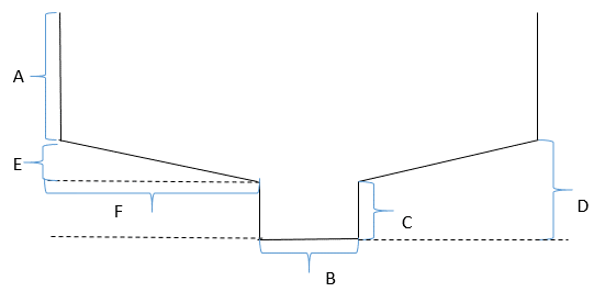
| Clarifier – Circular Schematic | |||
| Bottom Slope | As per CPHEEO manual 1:8 to 1:12 | ||
| A | 3.50 | m | Including 0.5 m F.B. |
| B | m | 0.5 clearance around central shaft | |
| C | m | ||
| D | 1.48 | m | |
| E | 0.48 | m | |
| F | 4.77 | m | |
| Secondary clarifier dimensions (May change in actual GAD – this is only tentative) | |||
 |
|||
| Feed Well | Tentative – verify with vendor | ||
| Diameter of feed well | 2.11 | m | 10-20 % of tank diameter as per CPHEEO Page 5-58 Section 5.7.4.2.7 Nov,2013 |
| Height of feed well | 2 | m | 1-2 m as per CPHEEO Page 5-58 Section 5.7.4.2.7 Nov,2013 |
| Downward velocity | 0.02 | m/s | |
| CHECK velocity | OK | No specifications in CPHEEO; <0.75 m/s as per Metcalf and Eddy Edition-5, Page-387, Section-5.6 | |
| Volume of feed well drum | 6.98 | cum | |
| HRT of feed well | 1.65 | min | |
| Sludge piping (Secondary Clarifier to RAS pump) | |||
| Sludge RAS flow per clarifier | 0.0116 | cum/sec | |
| Velocity of flow in pipe | m/s | ||
| C/S area of sludge removal pipe | 0.01 | sqm | |
| Diameter | 0.111 | m | |
| Diameter provided | 0.200 | m | |
| C/S area | 0.0314 | sqm | |
| Velocity during peak flowrate | 0.37 | m/s | |
| Velocity during 50% RAS of Average flowrate | 0.18 | m/s | Assuming 50% RAS flowrate; Should be 0.3-0.6 m/s as per CPHEEO manual |
| Velocity during 30 % RAS | 0.11 | m/s | Assuming 30% RAS flowrate; Should be 0.3-0.6 m/s as per CPHEEO manual |
| At 50 % RAS flow of Average flow | Intermittent RAS flow Regulation required | ||
| At 30 % RAS flow of Average flow | Intermittent RAS flow Regulation required | ||
| RAS flow duration per hours @ 30% RAS flowrate | 18.00 | min/hr | |
| RAS flow duration per hours @ 50% RAS flowrate | 30.00 | min/hr | |
| Summary | |||
| Diameter | 10.54 | m | |
| Side water depth | 3.50 | m | |
| Free board | 0.3 | m | |
| Feed well diameter | 2.11 | m | |
| Feed well depth | 2 | m | |
| Width of launder | 0.29 | m | |
| Depth of launder incl free fall | 0.53 | m | |
| RAS pump capacity | 41.7 | cum/hr | |
| Bottom Slope | 0.10 | As per CPHEEO manual 1:8 to 1:12 | |
| A | 3.50 | m | Including 0.5 m F.B. |
| B | 1.00 | m | 0.5 clearance around central shaft |
| C | 1.00 | m | |
| D | 1.48 | m | |
| E | 0.48 | m | |
| F | 4.77 | m | |
| No of orifice | 53.00 | nos | Equally spaced along the launder inner side |
| Orifice diameter | 40.00 | mm | |
|
|||